1. Electron spin resonance (ESR) or electron paramagnetic resonance (EPR) spectroscopy is a method for studying materials which contain unpaired electrons. The basic concepts of EPR are analogous to those of nuclear magnetic resonance (NMR), except electron spins are excited instead of the spins of atomic nuclei. ESR spectroscopy is particularly useful for studying metal complexes or organic free radicals. ESR was first observed in Kazan State University by Soviet physicist Yevgeny Zavoisky in 1944, and was developed independently at the same time by Brebis Bleaney at the University of Oxford [wikipedia]. |
 |
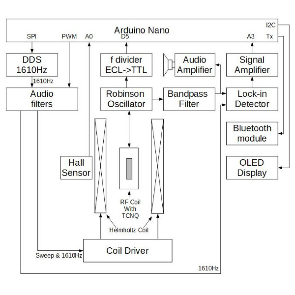 |
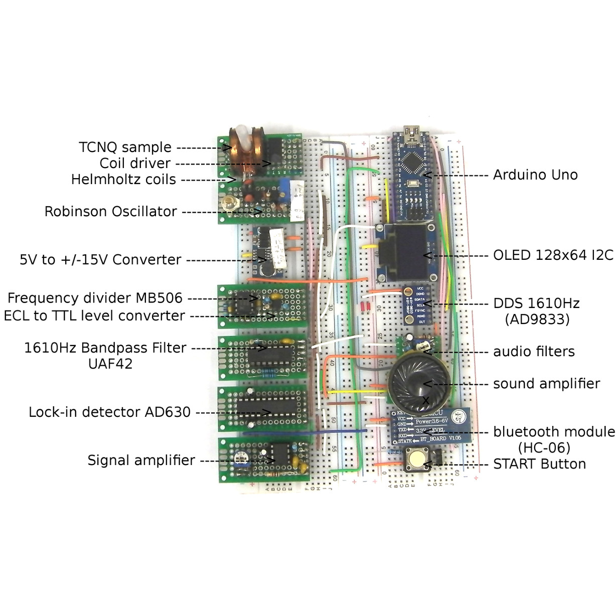
2. Block diagram. The aim of this experiment was to design and build a simplified USB powered ESR spectrometer. A sample of TCNQ is placed in a coil which is part of an LC circuit of a Robinson oscillator operating at 42Mhz. The signal output of the Robinson oscillator which has gone through a band pass filter (1610Hz) is connected to a lock-in detector. The detected signal is then connected to the analogue input of an Arduino Nano. The frequency output of the Robinson oscillator, which has gone through a frequency divider and an ECL to TTL converter, is connected to the 16-bit hardware Timer1 of Arduino Nano. The second modulation signal (1610Hz) is produced by a direct digital synthesis. An external magnetic field (0-2mT) is produced by a miniature Helmholtz coil with an internal coil diameter of 12mm, and controlled through a coil driver by a PWM signal from an Arduino Nano. The ESR signal can be observed on a PC (RS232), any android device (Bluetooth), or a built-in 0.96 inch OLED display. Additionally the noise and the "butterfly signal" can be listened to, as an audio from a speaker with amplifier connected to the output of the bandpass filter. |
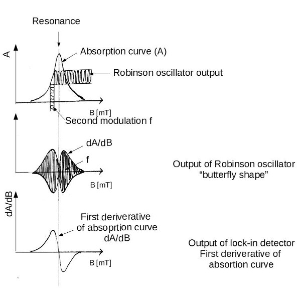
3. Second Modulation. To observe electron spin resonance, a sample containing unpaired electrons is placed in a resonator which is driven by a continuous, constant frequency, low power signal. In order to detect the ESR signal, an external magnetic field is swept slowly. To improve sensitivity, an additional oscillating magnetic field - second modulation - is applied to the external magnetic field. As a result of the second modulation, a characteristic "butterfly signal" is observed at the detector output. After the lock-in detection, only the signal with a frequency identical to the second modulation is detected and recorded as its first deriverative with respect to external magnetic field. If the excitation of the radio frequency is 42Mhz, the magnetic field strength required for resonance would be approximately 1.5mT. |
 |
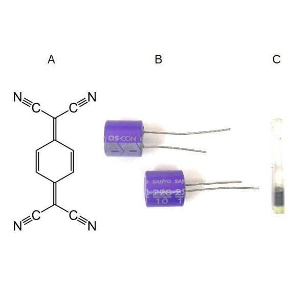 |
4. TCNQ (tetracyanoquinodimethane) sample was extracted from a 220uF/10V solid state OS-CON Sanyo electrolytic capacitor and sealed in a plastic tube with a diameter of 5mm. The sample used for these experiments contains around 300mg of solid organic electrolyte. TCNQ is a charge transfer salt organic conductor. OS-CON series capacitors used the charge transfer salt TTF-TCNQ as a solid organic electrolyte. By 1995, the Sanyo OS-CON became the preferred decoupling capacitor for Pentium processor-based IBM personal computers. The Sanyo OS-CON e-cap product line was sold in 2010 to Panasonic, which replaced the TCNQ salt with a conducting polymer under the same brand [wikipedia]. The extraction of TCNQ from an OS-CON capacitor must be supervised by a scientist and an engineer, who is experienced and skilled with respect to this process, and who will assume full responsibility for the safety of those involved. TCNQ and TTF may be regarded as low-toxicity compounds [link], however solid organic electrolytes may contain other toxic compounds. |
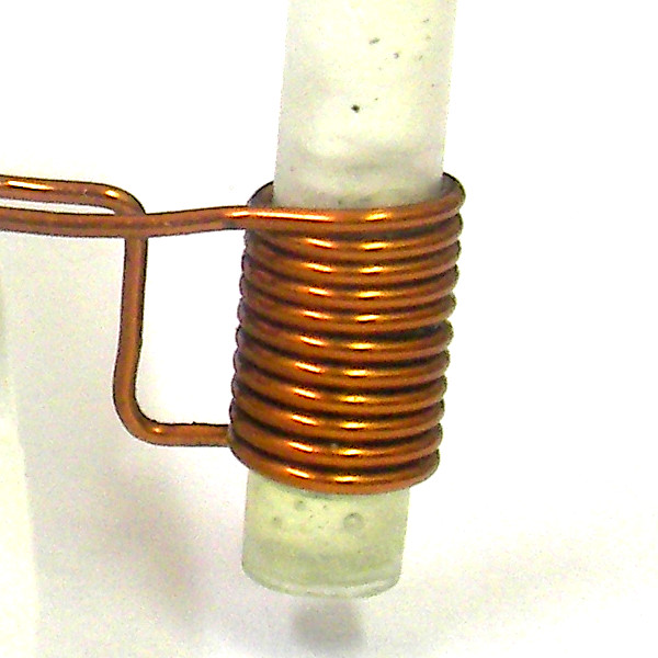
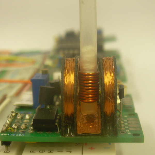
5. RF coil. The resonator consists of a coil (internal diameter 5mm, 11 turns, 0.7mm Enamelled Copper Wire) and 30pF capacitor. |
 |
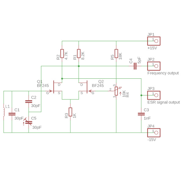 |
6. Robinson Oscillator. The FET Robinson oscillator circuit consists of a limited self-oscillator, where seperate stages are used for regeneration and amplitude control. The essence of the Robinson system is that the only non-linearity in it occurs in the form of a simple limiter, such that both the oscillation conditions and the sensitivity to magnetic resonance absorption are predictable in a straight forward way. This is not the case in other forms of self-oscillating detectors, which are maintained in a more or less unpredictable or 'marginal' mode by the arbitrary operation of a manual or automatic control system [reference]. |
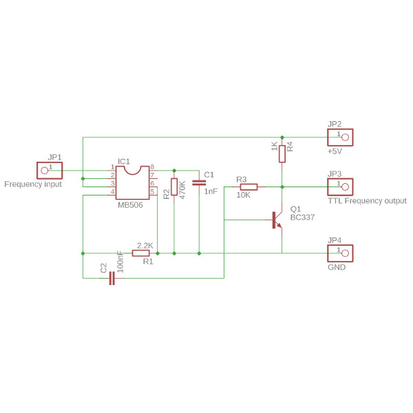
7. Frequency divider. The frequency of the Robinson oscillator is divided by 128. MB506 (Fujitsu) high frequency prescaler with max frequency of 2.4GHz is used. The prescaler output of 1.6V (ECL level) is converted to 5V (TTL level) using a BC337 transistor. |
 |
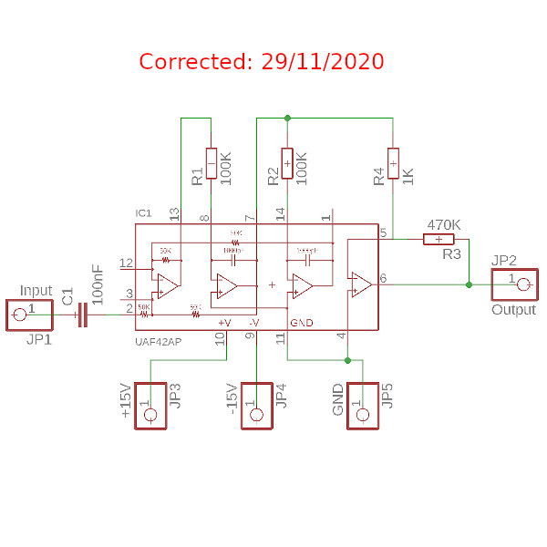 |
8. Band pass filter. The ESR signal from the Robinson oscillator ("butterfly signal) is connected to a band pass filter (UAF42 -Texas Instruments - it is a universal active filter configured for 1610Hz band pass filters). |
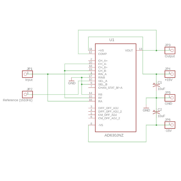
9. Lock-in detector. A very simple lock-in detector was built using an AD630 (Analog Devices) modulator-demodulator integrated circuit. More information on how to build a lock-in detector/amplifier can be found [here] and [here]. A lock-in amplifier is a type of amplifier that can extract a signal with a known carrier wave from an extremely noisy environment. Depending on the dynamic reserve of the instrument, signals up to 1 million times smaller than the noise components, potentially fairly close by with regards to frequency, can still be reliably detected [wikipedia]. Further information about lock-in detection can be found [link]. |
 |
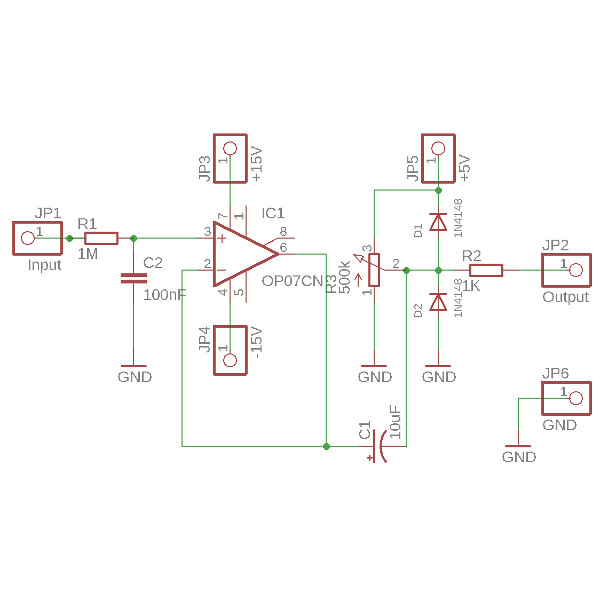 |
10. Signal amplifier. The key component of this circuit is a voltage follower (OP-07), with R3 equal to 500KOhm in order to adjust zero and two 1n4148 diodes to protect the Arduino Nano analogue input. |
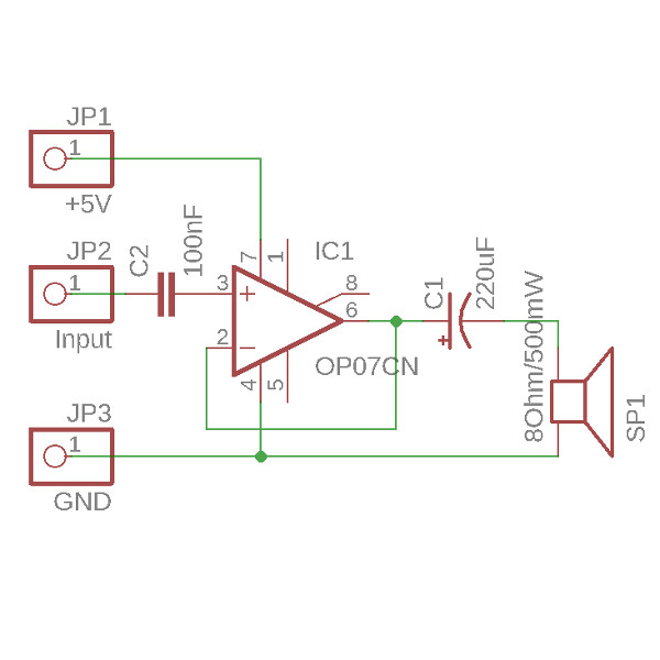
11. Audio amplifier. The modulated (1610Hz) ESR signal from the band pass filter is connected to an OP-07 op-amp in the voltage follower configuration. A small 0.5W/8Ohm speaker allows listening to the "butterfly signal" when the external magnetic field is swept through resonance conditions. |
 |
 |
12. Helmholtz Coils. The coil bobbin was designed in TinkerCAD and can be downloaded for 3D printing from [here]. The coil bobbin was 3D printed on a generic Prusa i3 printer using a 1.75mm PLA filament. The coil consists of 2 x 300 turns of 0.15 mm enamelled copper wire, with an internal diameter of 12mm. |
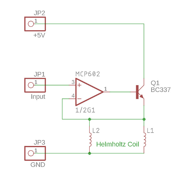
13. The Coil Driver consist of a voltage follower (MCP602 - Microchip) boosted with a transistor (BC337). Together, with the Helmholtz coil described above, when powered from 5V it can produce up to 2mT of an external magnetic field. |
 |
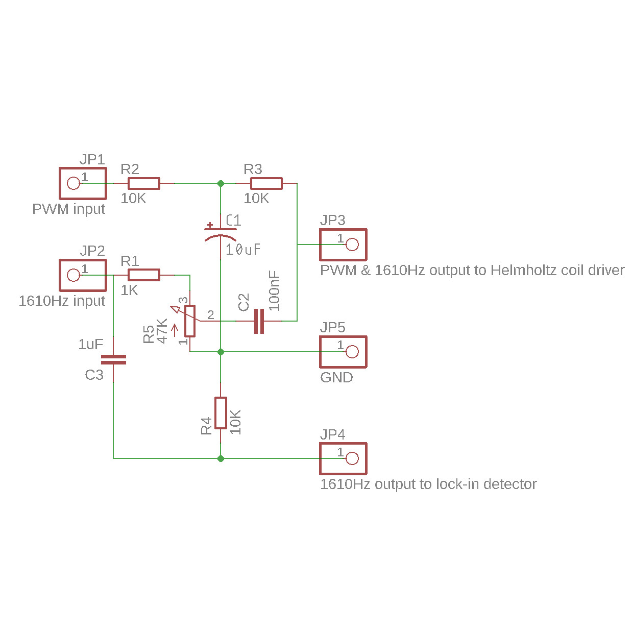 |
14. Audio Filters. This module has two inputs: one for the PWM signal to slowly sweep external magnetic field and another for 1610Hz from the Direct Digital synthesis module (second modulation). This module also has two outputs: one for the coil driver - a slow sweep signal with an added 1610Hz second modulation signal; and another 1610Hz reference signal for the lock-in detector. |
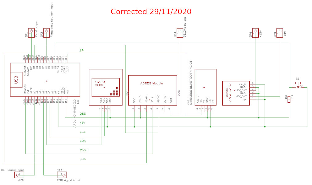 | |
15. The Digital part of this system (circuit above)) is based on an Arduino Nano. The OLED display is connected by an I2C bus. The direct digital synthesis based on the AD9833 is connected by an SPI bus, and a bluetooth module (HC-06) is the serial communication. The A1 analogue input is connected to the Hall sensor, the A2 analogue input to the signal amplifier (ESR signal), D5 is the digital input for Timer1 for frequency measurement, and D10 is a digital PWM output for sweeping the magnetic field. | |
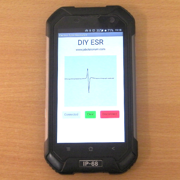 |
16. An Android Application allows any android device to be used as a display. The application can be downloaded from [here]. |
17. The ESR spectrometer was assembled on a breadboard. Each of the above described modules was soldered on universal PCB. The ESR signal was observed at f = 42Mhz for B=1,5mT. |
 |